 +86-27-87981730
 ovmc@ggjlz.com
 +86-27-87981730
 ovmc@ggjlz.com

Contact Us
 +86-27-87981730
 +86-27-87981619
 ovmc@ggjlz.com
  80# Fifth Hi-tech Avenue,East Lake Hi-tech Development zone,Wuhan,China
 1. Background Introduction
The gyroscope is the core component of the inertial system. It is used to measure the relative inertial space of the moving carrier to the angular velocity due to angular motion. It can be obtained by combining the displacement and linear velocity generated by the linear velocity measured by the accelerometer and other operations. Carrier real-time posture, speed, position and other information.
The basic principle of the fiber optic gyroscope is the Sagnac effect proposed by G. Sagnac in 1913, that is, the phase difference between two light waves propagating in the opposite direction along a closed circuit is proportional to the input angular velocity of the normal direction of the closed light path. Nearly 40 years have passed since the concept of fiber optic gyroscope was first proposed in 1976 and it was realized experimentally. The development of fiber optic gyroscope has also made considerable progress, and its development has also benefited from fiber optic communication in recent years. The rapid development of the field has greatly improved the stability and reliability of optical components.
Compared with other types of gyroscopes, the main advantages of fiber optic gyroscopes are mainly reflected in the aspects of small size, light weight, low power consumption, long life, high reliability, and mass production. The proportion of applications has increased year by year. The application of fiber optic gyroscope is mainly embodied in the three aspects of positioning, attitude control and absolute measurement. It has a vital military role, and it also has irreplaceable advantages in the civilian field.
2. Working Principle of Optical Fiber Gyroscope
Fiber optic gyroscopes can be divided into three categories according to their working principles, namely, interference type, resonance type, and Brillouin type fiber optic gyroscopes. The latter two were proposed later and have not yet been put into practical use. The currently used fiber optic gyroscopes are basically of the interferometric type. Because the length of the sensing fiber can reach several kilometers using a specific fiber winding method, the sensitivity of the fiber optic gyroscope can also meet the needs of medium and low-precision gyroscopes. However, there are still many difficulties to further improve the accuracy, mainly due to the constraints of temperature stability, etc., there is still room for further development in the direction of high accuracy.
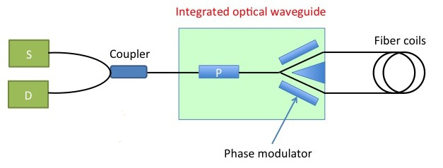
Fiber optic gyroscope includes an optical part and a signal processing part. The structure diagram of the optical part of a common fiber optic gyroscope using integrated optical waveguides is shown below.

Figure 1: Partial structure diagram of the optical path of the interferometric fiber optic gyroscope. S: light source; D: detector; Coupler: coupler; P: polarization control.
a) Light source selection
The light source provides the required optical signal for the fiber optic gyroscope, and the factors affecting the accuracy of the fiber optic gyroscope mainly include: optical wavelength stability, power stability, and polarization stability. Currently, the commonly used optical fiber gyroscope light sources are Super-Luminescent Diode (SLD) and Amplified Spontaneous Emission (ASE) using erbium-doped fiber.
The average wavelength stability of the SLD light source is poor, and it is suitable for use in low-precision fiber optic gyroscopes. The ASE light source has greatly improved the spectral width and spectral stability compared with the SLD light source, and the output power is also very high. The basic principle of the ASE light source is to amplify the spontaneous radiation signal generated by the erbium-doped fiber under the action of the pump light. The structure diagram of the ASE light source adopting the double-pass backward structure is as follows: The specific structure is shown in the figure below:
Figure 2: ASE light source structure diagram.
980nm pump;
WDM(Wavelength Division Multiplexing):980/1550nm wavelength division multiplexer;
EDF(Er-Doped Fiber);
FRM(Fiber Rotation Mirror);
ISO(Isolator);
Filter.
b) Polarization control
Polarization fluctuation is one of the key factors affecting the performance of the gyroscope. In order to control the drift caused by polarization instability in the fiber optic gyroscope, the fiber coil usually adopts the polarization maintaining fiber, so the components in the optical path part also need to use the polarization device, such as the polarization maintaining coupler, the polarization maintaining isolator, etc., in the integrated optical path The polarization control part is a polarizer, which can ensure that the performance of the gyroscope is greatly improved, but the cost is also higher.
In addition, depolarization technology can also be used, so that the fiber coil only needs to use ordinary single-mode fiber, the components in the optical path part do not need to use polarization-maintaining devices, and the polarization control devices need to use fiber depolarizers.
3. Matters needing attention
If the polarization-maintaining scheme is adopted, it is difficult to align the polarization main axis of the polarization-maintaining fiber during actual operation, and a dedicated polarization fiber fusion splicer must be used for fusion splicing between fibers.


Tel:+86-27-87981730 Email:ovmc@ggjlz.com,yuyan@ggjlz.com Address:80# Fifth Hi-tech Avenue,East Lake Hi-tech Development zone,Wuhan,China Zip code:430205 Technical Support:金百瑞
©2017Optics Valley Metering & Calibration Co.,Ltd ALL RIGHT RESERVED鄂ICP备17005403号-1 鄂公网安备 42011102002761号